Energy Saving Device (ESD) Datasheet
Please refer to our wiring diagrams below for more information.
Introduction
- RFID MIFARE technology
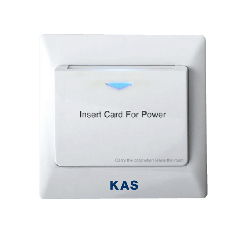
Figure 01
 ESD Image
Technical Specifications
|
Voltage |
100-240V AC 50-60Hz |
|
Number of Switching Relays |
2 [Mains Power, A/C Air Conditioner] |
|
Mains Power Switching Relay |
Rated to 40A |
|
A/C Switching Relay |
Dry contact (3 coloured wires) |
|
Reed Switch |
Dry contact (2 black wires) |
|
Working Temp |
-10C to 60C |
|
Working Humidity |
10% – 95% RH |
|
Dimensions |
W86mm x H86mm x D46mm (Bounding box) |
|
Card Read Time |
<0.8s |
|
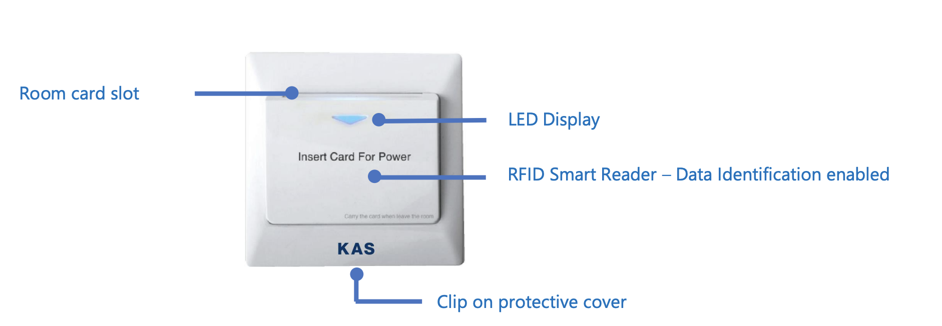
LED Display |
ON when no card is present, OFF when card is present |
|
User interface |
1 x Blue LED |
|
Data Identification enabled |
Yes (Mifare Sector 1) |
|
Colour |
White |
|
Installation fitment |
Mounting C-Clip supplied |
|
Default egress time delay |
15 seconds (Adjustable to optional 30 seconds) |
|
Australian SAA certified |
Yes |
Data Identification
Data Identification (DI) allows the room key to activate the ESD only. The room keys are encrypted when shipped from KAS. Data Identification is Standard for all ESD models.
|
Cards to activate ESD:
|
Cards that does NOT activate ESD:
|
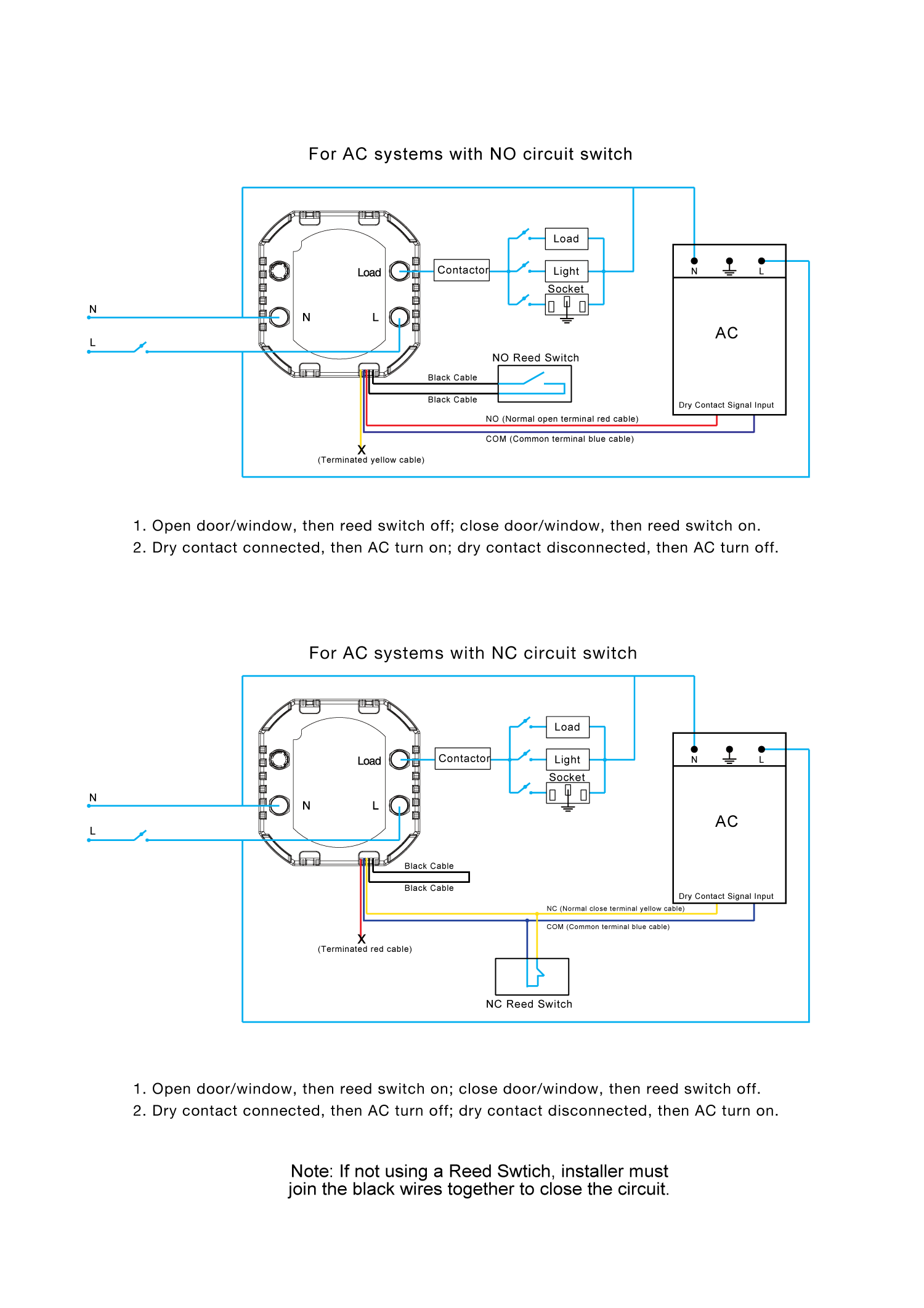
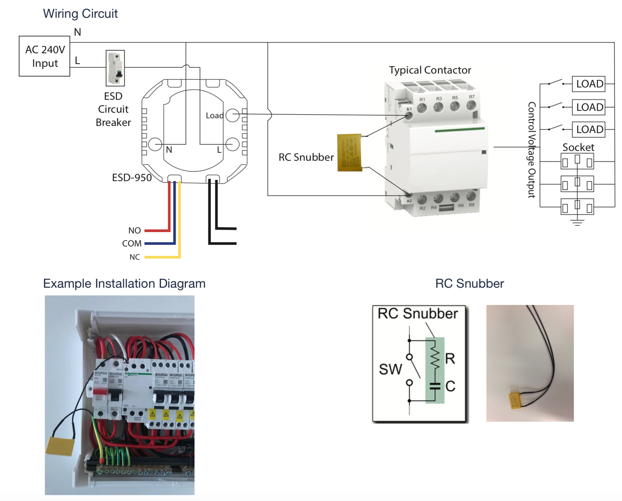
Wiring Diagram

Installation Fixture
|
Application: To securely mount the Energy Saving Device to a Gyprock or Plaster board wall. Hole Dimensions: 54 mm x 54 mm Suitable Wall Board Thickness: 10 mm-13 mm thickness |
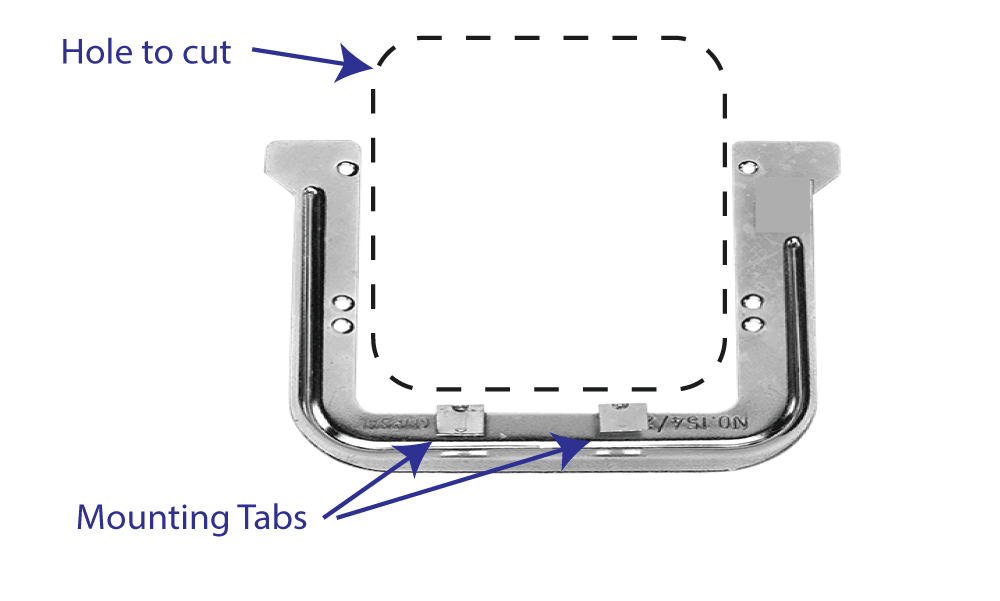
Installation Fixture Instructions:
- Locate the required position normally inside the entrance door.
- Trace internal C-Clip shape on the wall and mark screw holes
- Cut out the square with a gyprock saw – and cut out slots for the screw holes.
- Wire the ESD, and use screws fix onto the plaster wall using the screw holes on the C-Clip.
- Turn C-Clip upside down, line up the screw holes and trace the internal C-Clip shape again to form a square
- Insert C-Clip through the hole holding onto the 2 tabs that are coming off the bottom of the C-Clip facing the installer and fix the mounting tabs onto the plaster/gyprock wall.
RC Snubber

It is recommended that ESDs are installed with an RC Snubber across the switching contact. Please see ESD-Addendum-RC Snubber technical note for more information.
RC Snubber component is provided with each ESD.
Pre-Wiring Requirements
The following items are the pre-wiring requirements for each room. Please supply this information to your electrical contractor during the wiring planning phase and well prior to the electrical installation phase.
For any additional information please contact KAS Technical Support.
- 240V AC power supply cable to power the ESD. The normal location for the ESD is normally just inside the main entrance door close to the light switches.
- 1 x Twin 240V electrical cable from the ESD location to the sub-board contactor (relay) for lights/power control.
- 1 x Twin cable running from the ESD location to the A/C unit (Cat-5 cable suitable).
- 1 x Twin figure 8 speaker wire running from ESD location to desired reed switch locations (connected in series)
Electrician to Supply
- 240V Contactor(s) (relays) to sub-board for power and lighting control
- Any additional dry contact activated relays that may be required at the A/C unit
- Cabling to all locations
KAS Supply
- Energy Saving Device
- RC Snubber (Yellow) for each ESD
- Mounting C-Clips
- Fixing Screws
- Reed switches (as per quotation)
- Optional: Data Identification Programming Card (as per quotation)