-
Electronic locks are sensitive and advanced products with fragile microchips and hardware. Please be aware that the position and type of environment the lock is installed in can affect its lifespan.
-
To install the lock, we recommend professional carpenters or builders. Incorrect installation of the lock can lead to irreparable damage and void of warranty.
-
After the lock is installed, please change the default management pin code immediately and keep a record of your new code.
-
Keep the backup mechanical keys in a safe secure location which can be conveniently accessed if required.
-
A low voltage alarm will sound when the 4 x AA batteries need replacing.
-
Make sure the batteries are in the correct positive/negative terminals. Incorrect positioning of the batteries may short circuit and permanently damage the lock.
-
Please read the manual carefully before use, and operate the lock according to instructions.
-
User data will be retained if batteries are temporarily removed.
-
Low voltage warning will sound after each ‘unlock’ if battery voltage is below 4.8V.
-
Disclaimer: Figures and characters in this manual are for manual demonstration and may not reflect the exact type or style of each model. We reserve the right to display any product that best demonstrates the manual content.

Installation Video
|
Determine your door opening direction from the image provided
Use this direction to set the handle orientation the lock.
|
 |
 |
 |
Left Handle
|
Right Handle
|
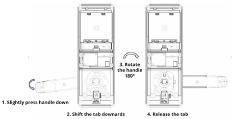
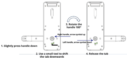
Reverse Handle Direction
-
To reverse the handle direction, you DO NOT need to fully unscrew the lock.
-
You can reverse the handles by shifting the tab downwards by using a small screw driver
-
Fully unscrewing the lock may void warranty.
 |
 |
Rear Handle
|
Front Handle
|
Square Spindle Assembly
-
Assemble the square spindle in the front handle and fix it with the split pin provided.
-
Ensure the arrow symbol on the clutch piece is point UP or DOWN
IMPORTANT: Ensure the arrow symbol is facing vertically for ‘right’ or ‘left’ handle direction, respectively. If installed incorrectly, you might need to damage the lock for entry. 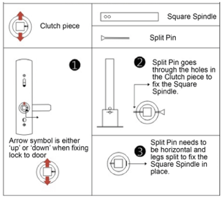
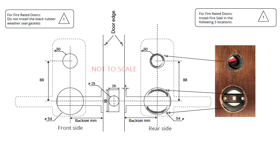
Drilling Instructions
- Ensure the drill holes are perpendicular to the door.
- check the dimensions physically incase the template is not to scale.
- Incorrect backset alignment may damage to the locks function and durability.
- Using In the drilling template provided mark the holes
- Drill or Utilise the existing 1 x 54 mm hole which is the standard cutting for a regular handle lockset.
- Drill the 1 x 30mm hole above the 54 mm hole from both sides to avoid damaging the door.
- Mark out and chisel a recess for the tubular latch finishing plate.
- Mark out and chisel the striker plate on the door frame.
Standard Lock Hardware Installation
- Loosely install the tubular latch
- NOTE: After installing the Tubular Latch, ensure any debris or dirt are cleaned out. Failure to do so may damage the latch and affect your warranty.
- Fit the front handle and install the square spindle with the provided split pin. Ensure the square spindle is aligned with the square clutch in the tubular latch
- Pulling the wire through the hole in the rear fixing plate
- Screw the 3 screws into the rear fixing plate
- Plug in the wire to the rear handle and bunch the cable into the rear handle keeping the wire away from moving parts
- Fix the rear handle to the rear fixing plate
- Insert batteries and test lock function with mechanical keys and card/code
- Rotate front and rear handles to check the smoothness of the handle to ensure the entire system is not over tightened.
- If the lock is designed to connect to KAS Access:
- Turn the lock on and open the KAS Access App.
- Select "Setup" and then "Bluetooth Scan"
- Locate the lock’s serial number and pair it to the app.
- Go to "Locks", locate the lock and click it, Select "Edit Lock Name" and name the lock with an easily recognizable name (e.g. the door unit number).
- Once the lock is set up and ready to use, remove the clear plastic film that covers the keypad. Failure to do so will make it very difficult to remove in the future.

Fire Rated Lock Hardware Installation
- If you are installing this lock on a fire rated door, a separate fire rating kit is required for compliance.
- Rubber Gaskets must be removed from the lock at installation
- Loosely install the tubular latch
- Insert the fire rated seals in the holes
- Larger piece in the 30mm hole
- Smaller pieces ( x 2) in 54 mm hole, above and below the tubular latch
- Remove the rubber gasket seals from the locks bodies.
- Fit the front handle and install the square spindle with the provided split pin. Ensure the square spindle is aligned with the square clutch in the tubular latch
- Pulling the wire through the hole in the rear fixing plate
- Screw the 3 screws into the rear fixing plate
- Plug in the wire to the rear handle and bunch the cable into the rear handle keeping the wire away from moving parts
- Fix the rear handle to the rear fixing plate
- Insert batteries and test lock function with mechanical keys and card/code
- Rotate front and rear handles to check the smoothness of the handle to ensure the entire system is not over tightened.
Fire Rated Seal Locations
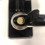
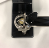
Mechanical Key Override
Flick the black cap covering the mechanical barrel on the front handle open
 The key cover is attached to the handle. Do not snap the black cap off.
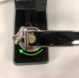
 - Insert the mechanical key. Turn it 90 degrees. This will retract the door latch.
- If the mechanical key does not turn, it is the wrong key.
- Try turning the key and handle at the same time to avoid breaking the mechanical key inside the cylinder.

External Backup power Supply (USB-B)
Maintenance
Troubleshooting
If you experiencing any of the following faults, please check this quick guide. For further support please contact KAS
|
E lectronic/System Malfunction
|
|
|
Latch Not Retracting
|
|
|
No Power
|
|
Next steps after Lock installation, please click the link below.
- Now your lock is installed! Click here (Android) or here (Apple) to get the app!