Requirements and Recommendations
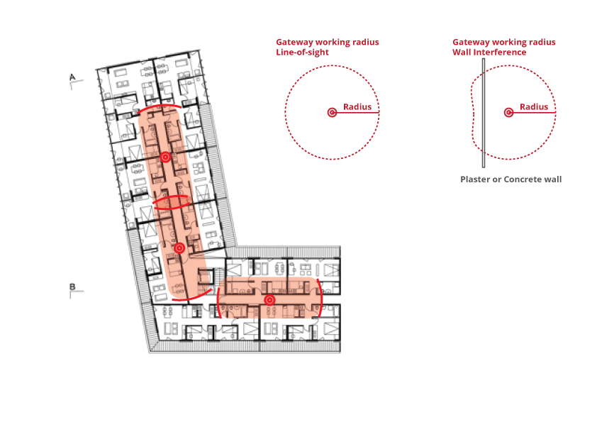
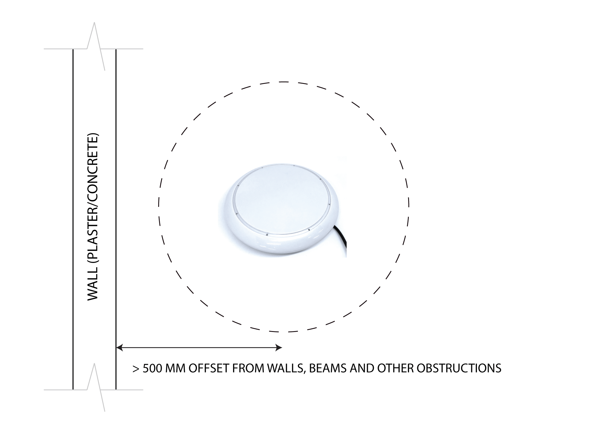
- location and distances for the best coverage
- obstructions that may affect the range of the gateway
- powering and connectivity requirements

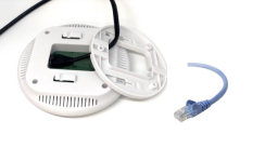
- Mount the gateway to the ceiling using the supplied bracket. (Clip on).
- Ensure the gateway is not covered or blocked by metal objects or any other obstructions such as concrete beams which could dramatically reduce the effective operating wireless range. Like any wireless protocol device, the optimal results will be achieved when within direct line of sight and the closest proximity (range) from the target devices.
- Connect the gateway to the network by either LAN cable (wired solution) or WIFI wireless solution (see below)
- Connect the power adapter to the gateway if not using LAN PoE (Power over Ethernet)
- The gateway must be installed in a location that will allow the operators easy access the occasional resetting or updating of WiFi credentials etc. It is also a requirement that the gateway be in a position to be able to see the LED light indicators.
- The signal strength for a gateway to all devices is strongly recommended to be = -70
- PoE Option: (LAN + Power Over Ethernet)
- WIFI Option: (DC Plug + WIFI)
- LAN Option: (DC plug + LAN cable)
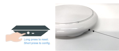
- Short press (3 seconds) The gateway will drop the current WIFI parameters.
- Return to the app and click ‘config’ to enter new WIFI parameters.
- Long press the button (10 seconds) on the side of the gateway.
- Upon factory reset the red LED will pulse once.
Gateway Positioning and Mapping

Range Guide for Gateway to Lock Hardware
| Obstruction |
Range *meters
|
|
Direct Line of Sight
|
10-15
|
| Obstructed (Drywall / Plaster board) etc |
8
|
|
Plastic / Glass / Wood Doors
|
8
|
|
Brick / Concrete Walls
|
5
|
| Strong winds / weather conditions |
Can affect range
|
|
Electrical Hardware
|
Can affect range
|
| Electrical Signals / Shadowing |
Can affect range
|
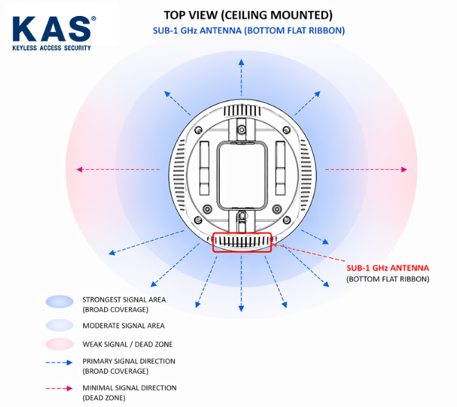
Angle recommendation for Gateway to Lock Hardware
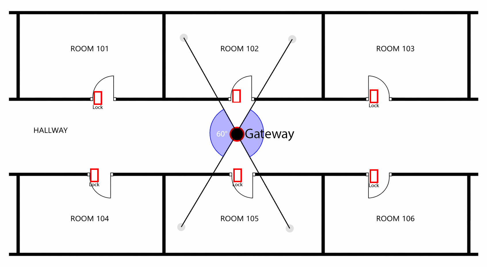
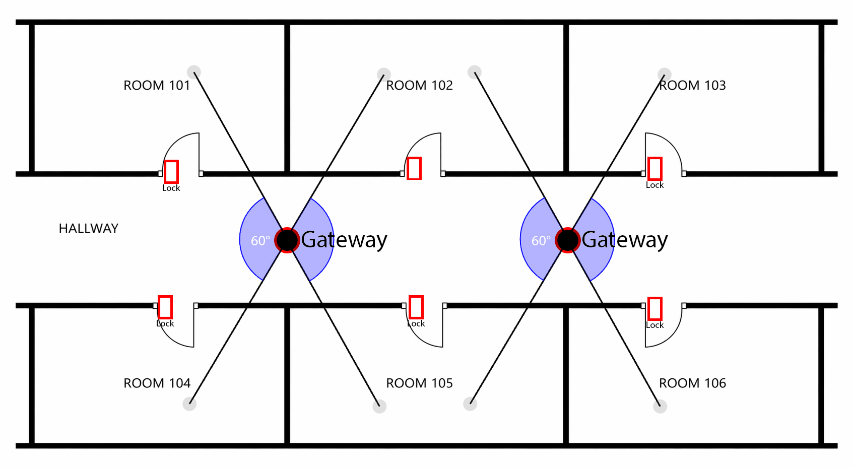
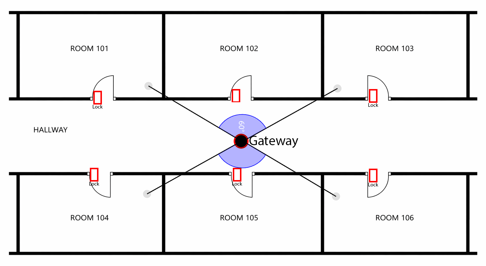
Example site plan
Notes and Disclaimers

Disclaimer:
KAS will not be held responsible or liable for any site internet connection issues relating to the internet connection between the KAS Gateways and the KAS Cloud servers (KAS Console / Access accounts). KAS hardware products including the Gateways which connect to the KAS lock remain under KAS standard warranty terms and conditions, however, the client’s site internet connectivity and related issues involving connection through the sites internet will be the responsibility of the client and/or their engaged IT/Network Manager and their selected Internet Service Provider. This disclaimer applies to all internet communications whether by WiFi, Cable and/or Mobile Network Routers.
While KAS will provide standard technical support services to assist with identifying such connectivity issues resulting from the KAS Gateway functionality to the KAS Locks (including Battery operated locks and the Access Control Readers), we are not responsible (or liable) for any unreliable (or failed) data transmission issues resulting from the KAS Gateways passing through the site’s internet, The resolution any site Internet issues remains the responsibility of the client and/or their own engaged IT personal and their Internet provider.
Configuration
 |
 |
 |
|
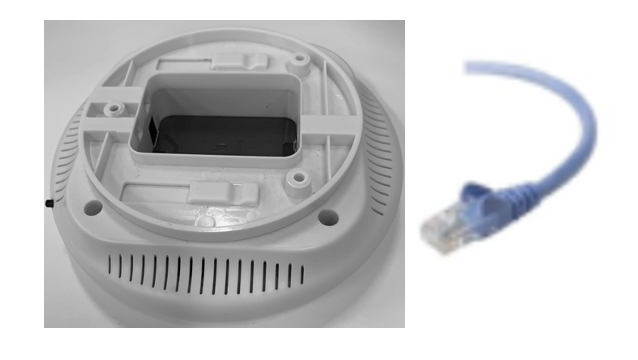
For PoE:
Plug the PoE LAN cable into the base of the gateway as pictured, this needs to be connected to your router. No power supply required.
|
For WIFI:
Plug the PC Plug into the base of the gateway as pictured.
5V DC power is required
|
For LAN:
Plug the LAN cable into the base of the gateway as pictured, this needs to be connected to your router.
5V DC power is required
|
 Red solid LED: Configuration Mode
 Red flashing LED: Connected the internet
 Green flashing LED: Connected to Wifi
 Green & Red flashing Connected to the internet via PoE
Setting up the gateway
KASAccess Web Interface (GEN2)
KAS Console Web Interface (GEN1)
Troubleshooting
How to Reset the Gateway