Information
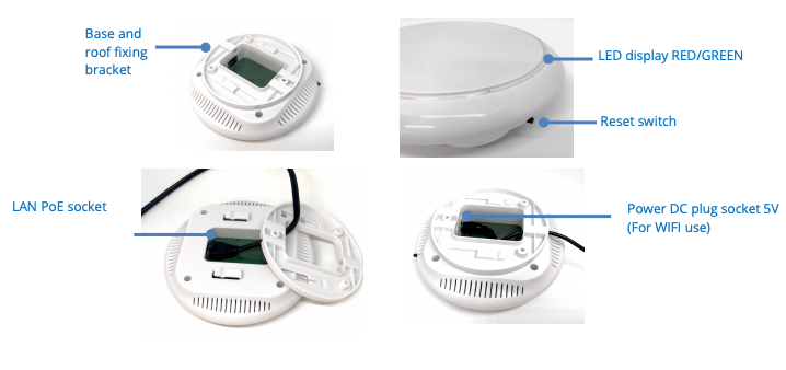
- Mount the gateway to the ceiling using the supplied bracket. (Clip on).
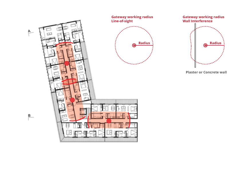
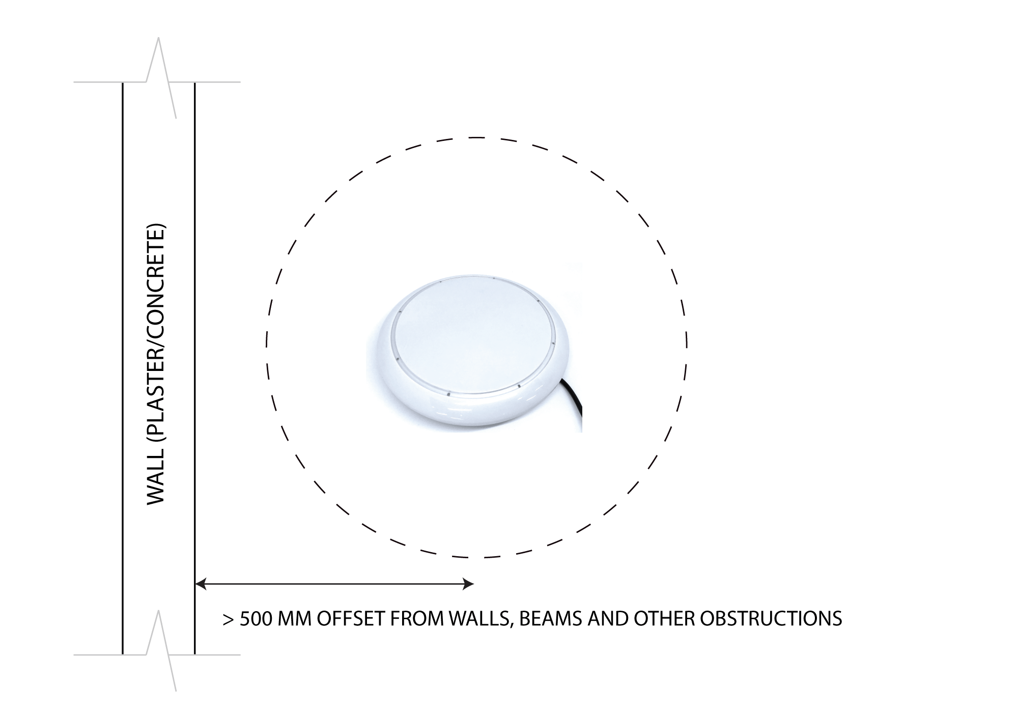
- Ensure the gateway is not covered or blocked by metal objects or any other obstructions such as concrete beams which could dramatically reduce the effective operating wireless range. Like any wireless protocol device, the optimal results will be achieved when within direct line of sight and the closest proximity (range) from the target devices.
- Connect the gateway to the network by either LAN cable (wired solution) or WIFI wireless solution (see below)
- Connect the power adapter to the gateway if not using LAN PoE (Power over Ethernet)
- The gateway must be installed in a location that will allow the operators easy access the occasional reseting or updating of WiFi credentials etc. It is also a requirement that the gateway be in a position to be able to see the LED light indicators.
- The signal strength for a gateway to all devices is strongly recommended to be = -70
Signal Loss
|
< -70 to 75
|
Excellent
|
|
< -75 to 80
|
Very Good
|
|
< -80 to 83
|
Good
|
|
> -83
|
Unreliable
|
Technical Specifications
|
Operating Temperature
|
-25 to 70
0C |
|
RF Frequencies
|
2.4 GHZ (BLE), 915MHz (Sub-1, AU)
|
|
Power Input
|
Min:5V Max:12V DC or PoE (Power over Ethernet LAN cable)
|
|
Peak Power Consumption
|
1A
|
|
Nominal Power Consumption
|
<340mA
|
|
Housing Dimensions
|
Diameter: 150 mm, Height: 40 mm
|
|
Weight
|
0.4 Kg
|
|
Mounting
|
Bracket installed onto the ceiling. Drop the LAN/Power cable through the center of the bracket and plug into the side of gateway.
|
|
Supply
|
Gateway, Fixing Bracket, 3 Screws
|
Images
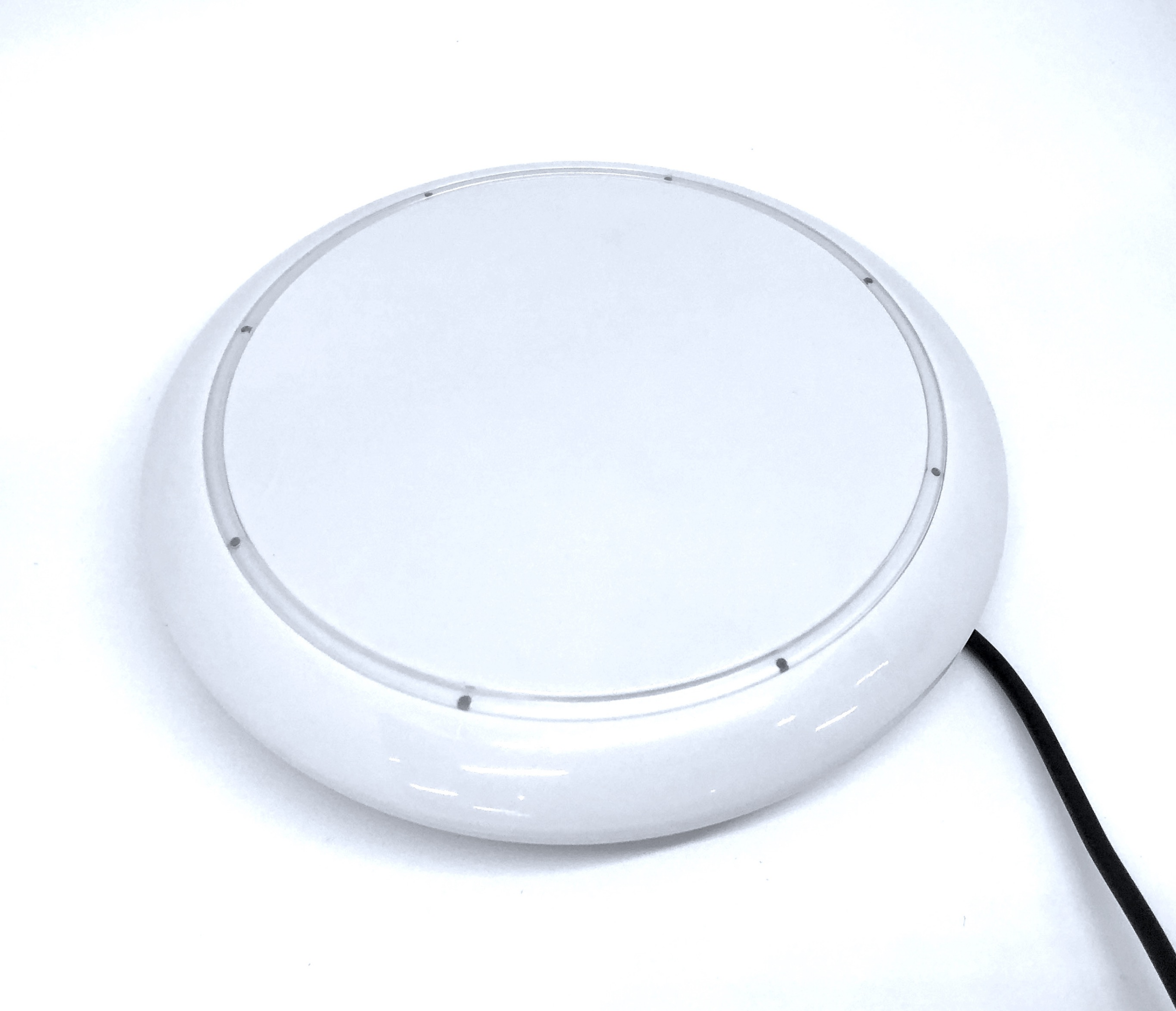
Top view: See the image on the front page.
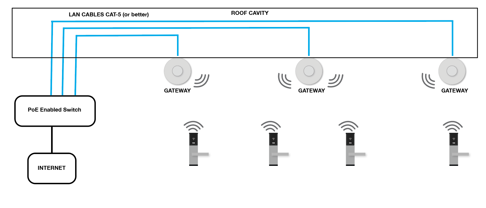
Wiring and Cabling
Option 1: LAN PoE (Preferred Option)
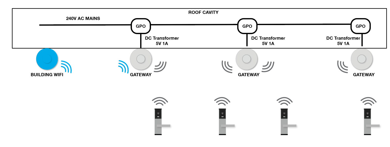
Option 2: WIFI + GPO – 240V AC Power Point with a AC/DC transformer
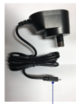
Power supply: AC/DC Transformer 5V 1A plug (if supplied):
Option 3: WIFI + DC Input – Connecting multiple gateways in series using a DC loop cable from remote DC Transformer
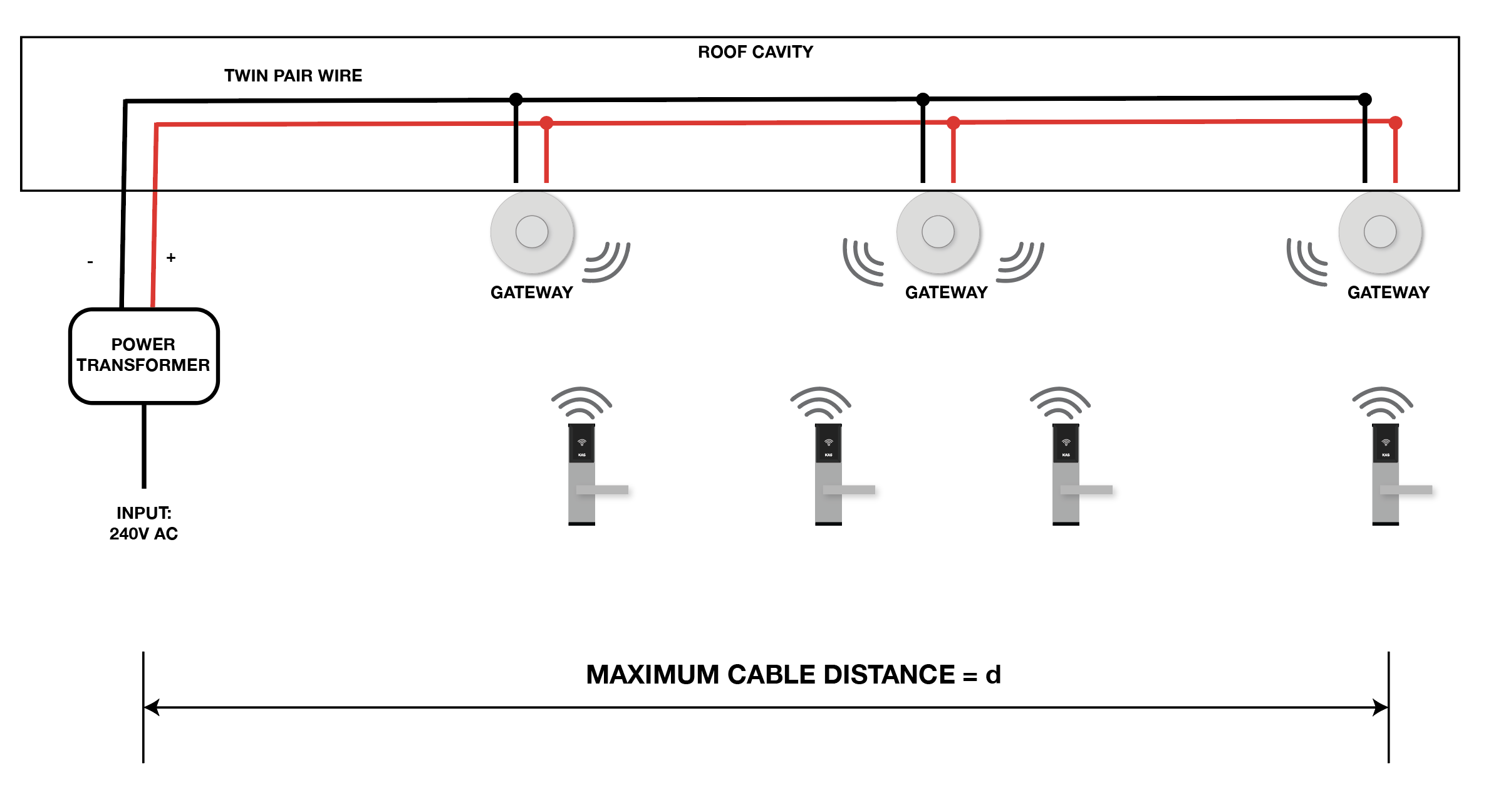
- Consider cable voltage drop if using Option 3.
- The maximum cable distance and approximate cable voltage drop can be calculated using the following design charts in Appendix A.
- See Appendix A to determine maximum cable distance and number of gateways per DC circuit.
Wiring and Network Decision Chart
|
Recommended Wiring
|
Strongly Recommended for new installations and sites with many gateways.(e.g greater than 4 gateways)
Option 1: LAN PoE
|
Recommended when installing a small amount of Gateways.
Option 2: GPO Power
|
Used for retrofit installation where LAN PoE is not possible.
Option 3: DC Circuit
|
|
Activate the Gateway with Mobile App using BL
E for initial configuration |
YES
|
YES
|
YES
|
|
Each gateway will have its own IP address which can be configured and power cycled remotely without visiting the device
|
YES
|
NO
|
NO
|
|
Gateway power cycles required to physically visit the gateway (sometimes enter roof cavities or comms rooms)
|
NO
|
YES
|
YES
|
|
Requires DHCP only network and stable WIFI connectivity (May need a custom SSID or manual whitelisting of gateway MAC address on network for stable connectivity)
|
NO
|
YES
|
YES
|
Gateway Positioning and Mapping
Maximum Number of Lock Hardware to a Gateway: 60 lock hardware to a gateway
Range Guide for Gateway to Lock Hardware
| Obstruction |
Range *meters
|
|
Direct Line of Sight
|
10-15
|
| Obstructed (Drywall / Plaster board) etc |
8
|
|
Plastic / Glass / Wood Doors
|
8
|
|
Brick / Concrete Walls
|
5
|
| Strong winds / weather conditions |
Can affects range
|
|
Electrical Hardware
|
Can affects range
|
| Electrical Signals / Shadowing |
Can affects range
|
Example site plan

Disclaimer:
KAS will not be held responsible or liable for any site internet connection issues relating to the internet connection between the KAS Gateways and the KAS Cloud servers (KAS Console accounts). KAS hardware products including the Gateways which connect to the KAS lock remain under KAS standard warranty terms and conditions, however, the client’s site internet connectivity and related issues involving connection through the sites internet will be the responsibility of the client and/or their engaged IT/Network Manager and their selected Internet Service Provider. This disclaimer applies to all internet communications whether by WiFi, Cable and/or Mobile Network Routers.
While KAS will provide standard technical support services to assist with identifying such connectivity issues resulting from the KAS Gateway functionality to the KAS Locks (including Battery operated locks and the Access Control Readers), we are not responsible (or liable) for any unreliable (or failed) data transmission issues resulting from the KAS Gateways passing through the site’s internet, The resolution any site Internet issues remains the responsibility of the client and/or their own engaged IT personal and their Internet provider.
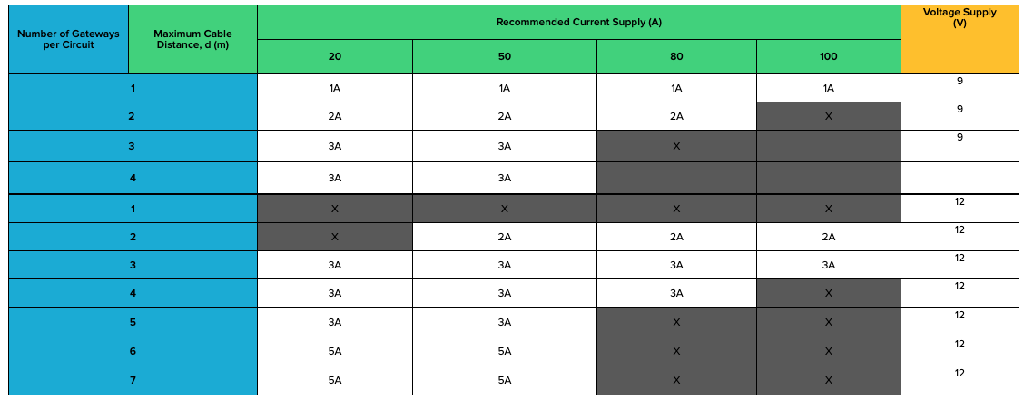
APPENDIX A – DC CIRCUIT DESIGN CHARTS
Table 1: DC Circuit Design Chart
- Cable specs are used in the below table: (1.04 mm-sq copper cable)
- Cable Length: is calculated as a one-way distance to the furthest gateway. Not round trip distance.
- Maximum Peak Gateway Current Draw: 500 mA
- Maximum Gateway Voltage Supply: 5V – 11V DC
Note: 12V DC Power supply should only be installed when you anticipate a high voltage drop.